2015年10月28日 星期三

Fortigate SSL VPN config

Fortigate Movie teach how to configuration the SSL VPN

https://www.youtube.com/watch?v=lqYbNqZSPRA

http://travelingpacket.com/2014/03/21/fortigate-fortios-5-0-6-ssl-vpn-configuration/

The best information available for anything fortinet is always found at docs.fortinet.com. This entry will show the needed steps to create a SSL VPN via the web interface.
Creating the SSL VPN has many working parts that come together to make one of the best Remote access VPNs out there. In this example we are creating a Split tunnel VPN, and enabling Tunnel mode.
The SSL VPN is one of the best features of the device, it has an open license, so you can have as many people connect as the device hardware supports. No crazy licensing for SSL VPN as with Cisco and Sonicwall. You can also utilize the VPN to get select information to users based on their AD security group. For example if you have a business with users traveling all the time, you might have a certain portal for one group of users and have their internal bookmarks and file shares, and completely different portal for office staff users.  Another great benifit is in the protocol itself, SSL is almost never blocked by outbound firewall policies. A lot of companies (hotels, hospitals) and educational institutions block IPSEC from leaving the network which stops your remote access VPN from connecting.
Steps:
1. Create Address object for SSL Subnet and Internal networks
2. Create route for new subnet
3. Create Users/User group for user authentication
4. Config the VPN Portal
5. Config the VPN settings
6. Create the SSL VPN policy, including the projected subnet for Split Tunnel.
7. Create policy to allow traffic from the Lan to SSL, and from SSL to Lan.
1. Create Address object for SSL Subnet and Internal networks
We will create an address object with the Subnet of our SSL VPN clients. I would recommend using a crazy private IP subnet as to not conflict with Home/work local subnets.
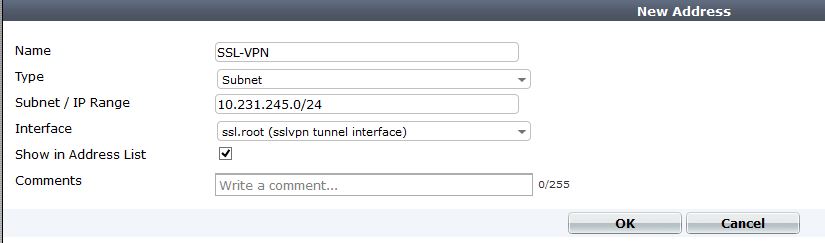
SSL-address
Then we need to create another object for our Protected subnet. This is our internal network that we want the remote user to be able to access. If there are multiple subnets it might be better to add an address object group.
internal-address
2. Create route for new VPN subnet
Since the SSL VPN is a “interface” we will route our subnet across of it. Notice our device is ssl.root, and that removes our needed gateway.
SSL-Route
3.  Create Users/User group for user authentication
There are many different ways to configure authentication within the device. You can authenticate VPN users against LDAP, Radius, or local accounts. In this example I am just using local accounts, but using LDAP or Radius is a much better option. You can use just individual users, or groups to authenticate to within the VPN policy. I would go ahead and create a User group so that you can add any local, radius, or ldap users into it in the future.
usergroup
I am creating a user group call SSL_VPN and in this case its just local. If I wanted to add a LDAP/Radius server to authenticate against, I could just add the remote server. If I wanted to get even more specific and say authenticate against a security group within LDAP I would just modify the remote server portion of the user group to add that.
4. Config the VPN Portal
The portal is the landing page of the SSL VPN. It is a great place to add book marks, shortcuts for RDP, or info for users. For example, we have an internal sharepoint site for users, by placing a link on the portal, users they just have to click and Whola, instant access. This is great because installing the VPN client which allows tunnel mode requires admin access to the PC. If a user is traveling or at a hotel they might not have this access. Other great uses are RDP session, and file shares. Both will launch in a Java applet window and allow you access to RDP/SMB.
SSL-Portal
We are using the “Full-access” Portal, this is just a name. I added the IP Pool for the clients to get tunnel addresses. You can customize the page to any specification. A note, you can also fully edit your VPN login page to reflect your company logo, etc. You can do this by adding in the feature under system – admin- features and enabling it.
5. Config the VPN settings
The VPN settings consists of the IP pool, Port used, encryption strength, and of course DNS/WINs servers. If you want to push your domain name so that DNS will resolve to this interface, its a CLI command. I will do another entry on it.
SSL-Config
6. Create the SSL VPN policy, including the projected subnet for Split Tunnel.
This is where we actually allow access from the internet to our VPN portal. It is also where we specify our Protected subnets, which are the subnets injected into the clients routing table. You can also specify what portal certain users will see. For example, if you had a group of teachers who needed to get to the Teacher portal, and an admins group that needs to have a different portal and ACL to get to all servers.
VPN-ACL
Notice we select VPN as type, then incoming interface. The Local protected subnets are what we are pushing into the routing table of our client.
Next create an new Authentication policy.
user-policy
From here select your user group that we created earlier, if you want individual users select those as well. You can also enable UTM if you feel its needed.
Now just save all the settings
7. Create policy to allow traffic from the Lan to SSL, and from SSL to Lan.
For the last step we need to create policies to allow traffic in both directions. By default all traffic is blocked between interfaces int he firewall. The SSL VPN is an interface, so we need to allow traffic to it.
Just create a policy with Source interface being ssl.root, and allow all traffic to your LAN (or however you see is best to secure) and then another policy from LAN to ssl.root.
Thats it! There are some optional configs dealing with Certs on both sides, and much stronger encryption methods.

Notes*
If you have a MPLS, or DMZ interface where you need  VPN clients to access you will have to create another VPN policy going from WAN to – DMZ, or WAN to MPLS and just mirror the WAN-to-lan SSL VPN policy. You will also have to modify the protected subnets with that interfaces network. If anyone has trouble with this feel comment and I will explain better.
On top of that you will need to create more ssl.root to DMZ and DMZ to ssl.root policies to allow access between the interfaces.

10 responses to “Fortigate Fortios 5.0 SSL VPN Configuration”

  1. Hobitt August 27, 2014 at 10:09 am
    Hallo,
    I have trouble with ssl vpn. I havel multiple ssl portals and I have multiple policy witch ssl vpn.
    When I connect via ssl vpn I get ip address 10.28.32.1 and I split route
    10.28.1.0/24 via 10.28.32.1 dev ppp0
    Ping to address 10.28.1.1 is OK:
    $ ping 10.28.1.1
    PING 10.28.1.1 (10.28.1.1) 56(84) bytes of data.
    64 bytes from 10.28.1.1: icmp_seq=1 ttl=249 time=11.1 ms
    64 bytes from 10.28.1.1: icmp_seq=2 ttl=249 time=6.13 ms
    64 bytes from 10.28.1.1: icmp_seq=3 ttl=249 time=19.1 ms
    But this traffic is translated by fortigate to address of internal interface:
    # diag debug flow show console enable
    show trace messages on console
    # diag debug flow trace start 100
    # diag debug enable
    # id=13 trace_id=23 msg=”vd-CUST received a packet(proto=1, 10.28.32.1:26621->10.28.1.1:8) fromssl.CUST. code=8, type=0, id=26621, seq=1.”
    id=13 trace_id=23 msg=”allocate a new session-008266b4″
    id=13 trace_id=23 msg=”find a route: flags=00000000 gw-172.21.1.1 via internal”
    id=13 trace_id=23 msg=”use addr/intf hash, len=3″
    id=13 trace_id=23 msg=”find SNAT: IP-172.21.1.254, port-62464″
    id=13 trace_id=23 msg=”Allowed by Policy-50: SNAT”
    id=13 trace_id=23 msg=”SNAT 10.28.32.1->172.21.1.254:62464″
    I do not understand, why fortigate translate this traffic?
    # diagnose sniffer packet any ‘host 10.28.1.1’ 4
    interfaces=[any]
    filters=[host 10.28.1.1]
    2.421885 ssl.CUST in 10.28.32.1 -> 10.28.1.1: icmp: echo request
    2.422775 internal out 172.21.1.254 -> 10.28.1.1: icmp: echo request
    2.427052 internal in 10.28.1.1 -> 172.21.1.254: icmp: echo reply
    2.427159 ssl.CUST out 10.28.1.1 -> 10.28.32.1: icmp: echo reply
    # config firewall policy
    (50) # show
    config firewall policy
    edit 50
    set srcintf “wan1_CUST”
    set dstintf “internal”
    set srcaddr “all”
    set dstaddr “LAN_net-BRANCH”
    set action ssl-vpn
    set identity-based enable
    config identity-based-policy
    edit 1
    set schedule “always”
    set utm-status enable
    set groups “Bilina_static”
    set users “test”
    set service “ALL”
    set sslvpn-portal “VPN_IP_BRANCH”
    set av-profile “default”
    set ips-sensor “default”
    set application-list “default”
    set profile-protocol-options “default”
    next
    end
    next

2015年10月7日 星期三

Windows backup script for personal in CUSCS

xcopy "d:\CUHK SCS\mailbox\*" n:\2_Albert\pcbk\mailbox

xcopy "d:\CUHK SCS\*" n:\2_Albert\pcbk\ /s /i

xcopy "d:\network\*" n:\2_Albert\SFire\ /s /i


xcopy C:\Users\alberthui\AppData\Roaming\Thunderbird\Profiles\dh0cxcuy.default\Mail\* n:\2_Albert\servermail /s /i

2015年9月22日 星期二

Linux ---Named install centos 6

https://www.digitalocean.com/community/tutorials/how-to-install-the-bind-dns-server-on-centos-6

How To Install the BIND DNS Server on CentOS 6


Preamble

This article will show you how to setup and configure the BIND DNS Server. If you are looking for a guide on how to use DigitalOcean's integrated DNS service, you may want to review the "How to Set Up a Host Name with DigitalOcean" article instead.
Before we begin, it is recommended you have at least two cloud servers to run your nameservers. Two nameservers are suggested to assure your primary and secondary servers are redundant in case of failure. You may want to consider using two different POP's as well. For example, we've used San Francisco 1 and New York 1. For the purpose of this guide, it will be assumed you are configuring both a primary and secondary name server.
It is worth noting that if you are managing a large number of domains this may not be the most viable solution, as you will need to manually add domains on both the master and slave nameservers. With that said, running your own nameservers is a great way to have more direct control over your hosting infrastructure, and assert full control over your DNS records.
As with any new server, it's always important to ensure your system is up to date. You can verify this by checking for updates using yum as follows:
yum update -y
(Note: In DigitalOcean, we call our cloud servers as "droplets". We will use both terms throughout this tutorial)

Initial BIND Installation

To begin, we will need to install the BIND and BIND Utilities packages using yum.
yum install bind bind-utils -y
Next, we'll open the BIND (named) configuration file and make several modifications.
nano -w /etc/named.conf
Your "options" section should appear as follows, replacing 2.2.2.2 with the IP of your second droplet.
options {
     #listen-on port 53 { 127.0.0.1; };
        listen-on-v6 port 53 { ::1; };
        directory "/var/named";
        dump-file "/var/named/data/cache_dump.db";
        statistics-file "/var/named/data/named_stats.txt";
        memstatistics-file "/var/named/data/named_mem_stats.txt";
  allow-query { any; };
        allow-transfer     { localhost; 2.2.2.2; };
        recursion no;

        dnssec-enable yes;
        dnssec-validation yes;
        dnssec-lookaside auto;

        /* Path to ISC DLV key */
        bindkeys-file "/etc/named.iscdlv.key";

        managed-keys-directory "/var/named/dynamic";
};
Above, listen-on must be commented to listen on all available interfaces. Recursion should be turned off to prevent your server from being abused in "reflection" DDoS attacks. The allow-transfer directive whitelists transfers to your secondary droplet's IP. Furthermore, we have changed the allow-query directive to "any" in order to allow users proper access to hosted zones.
Next, we'll want to add a new zone for our first domain, you should add the following to your named.conf below the existing zones.
        zone "mydomain.com" IN {
                type master;
                file "mydomain.com.zone";
                allow-update { none; };
        };
After saving named.conf with the changes above, we're ready to create our first zone file.

Configure BIND Zones

Firstly, we'll need to open the zone file, using the name you specified in the configuration above. (Ex: mydomain.com.zone)
nano -w /var/named/mydomain.com.zone
We'll add the following contents to our newly created file. You should replace the applicable information with your own, where 1.1.1.1 is the IP of your first droplet, 2.2.2.2 is the IP of your second droplet and 3.3.3.3 is the IP you wish to point the domain itself to, such as a droplet running a webserver. You are free to add additional entries in the same format.
$TTL 86400
@   IN  SOA     ns1.mydomain.com. root.mydomain.com. (
        2013042201  ;Serial
        3600        ;Refresh
        1800        ;Retry
        604800      ;Expire
        86400       ;Minimum TTL
)
; Specify our two nameservers
  IN NS  ns1.mydomain.com.
  IN NS  ns2.mydomain.com.
; Resolve nameserver hostnames to IP, replace with your two droplet IP addresses.
ns1  IN A  1.1.1.1
ns2  IN A  2.2.2.2

; Define hostname -> IP pairs which you wish to resolve
@  IN A  3.3.3.3
www  IN A  3.3.3.3
We can now start named for the first time. This may take several minutes while named generates therndc.key file, which only occurs on first execution.
service named restart
Once named has started successfully, we'll want to ensure that it is enabled as a startup service, by running the following:
chkconfig named on
By now, we should have a fully operational primary nameserver. You can verify that BIND is working correctly by running the following command, replacing 1.1.1.1 with the IP of your first droplet.
dig @1.1.1.1 mydomain.com
If you recieve a response which includes an answer and authority section, your nameserver has been configured correctly.

Slave Nameserver Configuration

With our primary nameserver configured, we'll now setup a slave nameserver on our second cloud server.
As always, please assure your system is up to date by checking for updates with yum as follows:
yum update -y
We can start by installing BIND (and related utilities) on the second droplet, in the same manner as the first:
yum install bind bind-utils -y
We'll proceed by opening named.conf and making the same changes we made previously, ommitting the "allow transfer" line. This directive is unnecessary as we will only be transfering records from our primary name server.
nano -w /etc/named.conf
options {
  #listen-on port 53 { 127.0.0.1; };
        listen-on-v6 port 53 { ::1; };
        directory "/var/named";
        dump-file "/var/named/data/cache_dump.db";
        statistics-file "/var/named/data/named_stats.txt";
        memstatistics-file "/var/named/data/named_mem_stats.txt";
  allow-query { any; };
        recursion no;

        dnssec-enable yes;
        dnssec-validation yes;
        dnssec-lookaside auto;

        /* Path to ISC DLV key */
        bindkeys-file "/etc/named.iscdlv.key";

        managed-keys-directory "/var/named/dynamic";
};
We will add the zone we configured on the first droplet, this time changing the "type" directive to slave, instead of master. You should replace "1.1.1.1" with your first droplet's IP address.
zone "mydomain.com" IN {
 type slave;
 masters { 1.1.1.1; };
 file "mydomain.com.zone";
};
After configuring our slave zone, we'll start named. Again this may take several minutes while our rndc.keyfile is initially generated.
service named start
As with the first cloud server, we want to assure named is set to run at startup with the following:
chkconfig named on
Your slave nameserver should now be up and running. You can verify that it is fully operational by usingdig again, replacing 2.2.2.2 with the IP of your second droplet.
dig @2.2.2.2 mydomain.com
After any changes you make to the master zone files, you will need to instruct BIND to reload. Remember, you must also increment the "serial" directive to ensure synchronicity between the master and slave.
To reload the zone files, we need to run the following command on the master nameserver, followed by the slave:
rndc reload

BIND in a chroot environment

It is generally advised to install the additional package "bind-chroot" which will drop the privileges of BIND into a chroot environment.
Luckily, the CentOS package makes this extremely simple. The only aspect worth noting is that active paths for BIND will change to their chrooted equivalents, for example /var/named becomes/var/named/chroot/var/named With CentOS 6, you will not need to move any files as the package automatically creates hard symlinks to the non-chrooted directories.
If you'd like to enable this feature for the added security which it provides, you can do the following:
yum install bind-chroot -y
service named restart

2015年9月21日 星期一

Linux how to install update SSH

http://www.tecmint.com/install-openssh-server-in-linux/

On RHEL/Centos/Fedora

Type the following yum command to install openssh client and server.
# yum -y install openssh-server openssh-clients

Configuration of OpenSSH

It’s time to configure our OpenSSH behaviour through the ssh config file, but before editing the/etc/ssh/sshd_config file we need to backup a copy of it, so in case we make any mistake we have the original copy.
Open a terminal and run the following command to make a copy of the original sshd configuration file.
$ sudo cp /etc/ssh/sshd_config  /etc/ssh/sshd_config.original_copy
As you can see from the command I typed, I added the original_copy suffix, so every time I see this file I know it is an original copy of the sshd config file.

 nc -v -z 127.0.0.1 22
Referring to the netcat results, the ssh service is running on port 22 on my machine. Very good! What if we want to use another port, instead of 22? We can do that by editing the sshd configuration file.
Set your OpenSSH to listen on TCP port 13 instead of the default TCP port 22. Open the sshd_config file with your favourite text editor and change the port directive to 13.
# What ports, IPs and protocols we listen for
Port 13
Restart OpenSSH server so the changes in config file can take place by typing the following command and runnetcat to verify if the port you set for listening is open or not.
$ sudo /etc/init.d/ssh restart
Should we verify is our openssh server is listening on port 13, or not?. This verification is necessary, so I am calling my lovely tool netcat to help me do the job.
# nc -v -z 127.0.0.1 13
Do you like to make your openssh server display a nice login banner? You can do it by modifying the content of/etc/issue.net file and adding the following line inside the sshd configuration file.
Banner /etc/issue.net

Linux copy folder command

http://www.cyberciti.biz/faq/copy-folder-linux-command-line/

Linux: HowTo Copy a Folder [ Command Line Option ]


I'm a new Linux user. How do I copy a directory or folder under Linux operating system using command line options and bash shell?

You can use various command to copy a folder under Linux operating systems.

cp Command

cp is a Linux command for copying files and directories. The syntax is as follows:
 
cp source destination
cp dir1 dir2
cp -option  source destination
cp -option1 -option2  source destination
 
In this example copy /home/vivek/letters folder and all its files to /usb/backup directory:
 
cp -avr /home/vivek/letters /usb/backup
 
Where,
  • -a : Preserve the specified attributes such as directory an file mode, ownership, timestamps, if possible additional attributes: context, links, xattr, all.
  • -v : Explain what is being done.
  • -r : Copy directories recursively.

Example

Copy a folder called /tmp/conf to /tmp/backup:
$ cp -avr /tmp/conf/ /tmp/backup
Sample outputs:
HowTO: Copy Folder Linux Terminal Command
Fig.01: cp command in action

rsync Command

You can also use rsync command which is a fast and extraordinarily versatile file copying tool. It can make copies across the network. The syntax is as follows:
 
rsync -av /path/to/source /path/to/destination
rsync -av /path/to/source/ /path/to/destination/source

2015年9月16日 星期三

CISCO NTP access group on the NTP client


NTP access group on the NTP client


we will use ntp access-group serve-only 15


  • Peer: Peer access-groups allow both request and control queries to be processed meaning the router will be allowed to update its time from the allowed peers.
  • Query-only: This only allows control queries to be accepted, control queries don’t actually the effect the date/time so I’m going to skip this one. See RFC 1305 for addition information about this.
  • Serve: Allows the router to reply to request as well as control queries.
  • Serve-only: Does not allow control queries and only replies to NTP requests.

access-list 15 remark NTP Peer Only ACL
access-list 15 permit host %{NTP_SERVER_PRIMARY}%
access-list 15 permit host %{NTP_SERVER_SECONDARY}%
access-list 15 deny any log
!
access-list 16 remark NTP Serve Only ACL
access-list 16 permit %{CLIENT_NETWORK}% %{CLIENT_WILDCARD}%
access-list 16 deny any log
!
ntp source %{NTP_SOURCE_INT}%
!
ntp authentication-key %{NTP_KEY_ID}% md5 %{NTP_KEY}%
ntp trusted-key %{NTP_KEY_ID}%
ntp authenticate
!
ntp access-group peer 15
ntp access-group serve-only 16
!
ntp server %{NTP_SERVER_PRIMARY}% key %{NTP_KEY_ID}% prefer
ntp server %{NTP_SERVER_SECONDARY}% key %{NTP_KEY_ID}%
!
ntp logging
ntp max-associations 4

CISCO Understanding the “NTP access-group” command in IOS

https://www.packet-forwarding.net/2013/06/02/understanding-the-ntp-access-group-command-in-ios/


NTP has always been one of those things I have found tricky to really lab up. Its fairly easy to setup, but verifying whether everything is working as you expect, can be hard because it takes a while to synchronize (and even unsynchronize).
In this post I will try and shed some light on the “ntp access-group” command set in Cisco IOS.
When you perform a “?” on the command set it looks like the following (on 12.2(33)SRD7):
1
2
3
4
5
R1(config)#ntp access-group ?
  peer        Provide full access
  query-only  Allow only control queries
  serve       Provide server and query access
  serve-only  Provide only server access
For each of the options you can specify an access-list:
1
2
3
R1(config)#ntp access-group peer ?
  <1-99>       Standard IP access list
  <1300-1999>  Standard IP access list (expanded range)
The trick to understanding how this lightweight security system works is to understand the following sentence in the documentation:
“If you specify any access groups, only the specified access is granted.”
Along with the ordered list of most open to least open:
1
2
3
4
peer
query-only
serve
serve-only
Lets illustrate this with an example. If you apply the following:
1
2
3
4
access-list 90 deny any
access-list 91 permit 10.1.2.10
ntp access-group peer 90
ntp access-group serve-only 91
What you are really doing is telling the router that it cant “peer” with anything (allow time requests and allow the system itself to synchronize). However processing of an incomming time request will go down the list and meet the “ntp access-group serve-only 91” command. This allows time requests from the hosts permitted in the access-list.
In our case host 10.1.2.10 can get its time from the local system.
The example above is for demonstration purposes since the “ntp access-group peer 90” is the same as not having specified the “ntp access-group peer” command in the first place.
So you see, an incomming request goes down the list of things “allowed” and if it finds itself allowed by anything, it succeeds. However if it reach the end of the list and nothing has permitted the request, it is discarded.
Caution
In my example, I have actually locked out any chance for the router itself to synchronize its time. This is due to the fact that since only peer and serve-only is allowed, and the only one of those two that will allow the router itself to synchronize is the peer option and this option denies everything.